
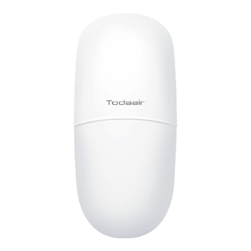
PRODUCT OVERVIEW
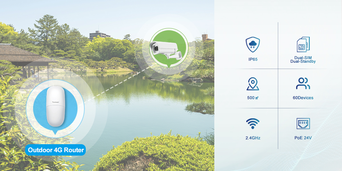
- With IEEE 802.11b/g/n standards
- With 500 ㎡ coverage range and 60 users connection
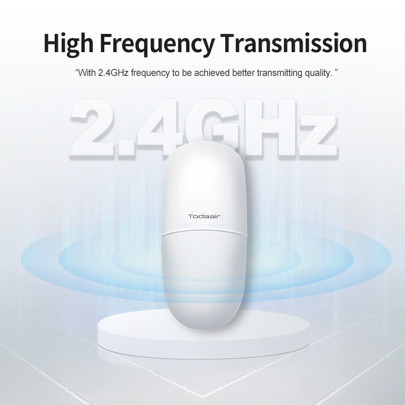
- With 2.4GHz frequency to be achieved better transmitting quality.
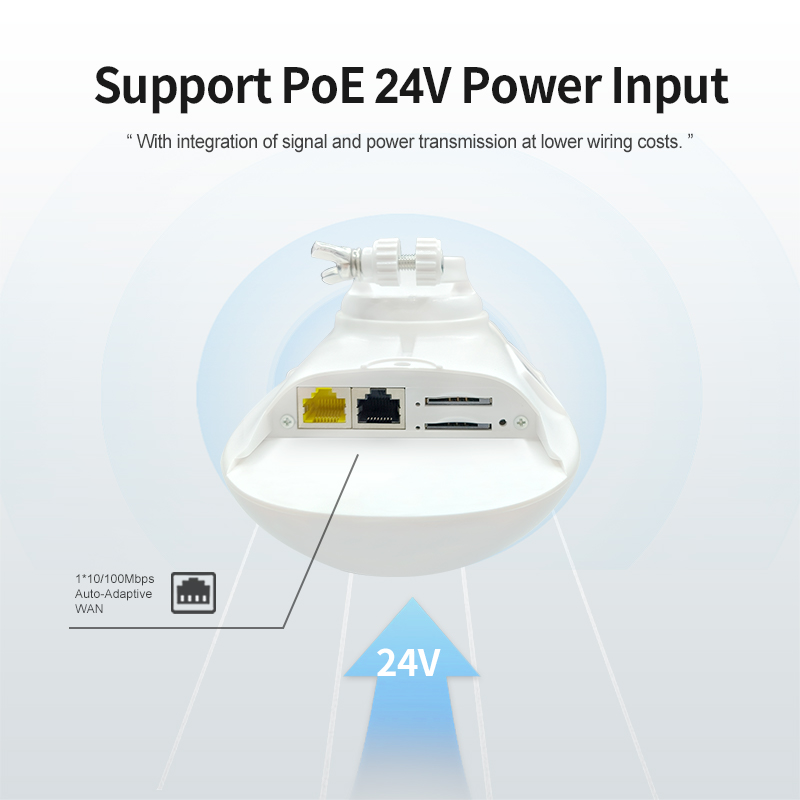
- Support PoE 24V power input
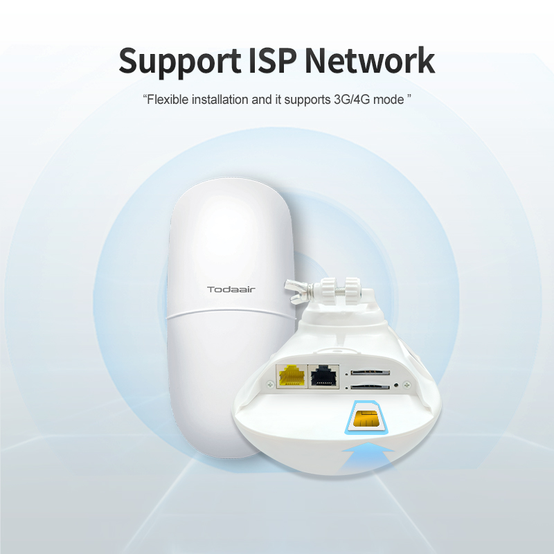
- Flexible installation and it supports 3G/4G mode
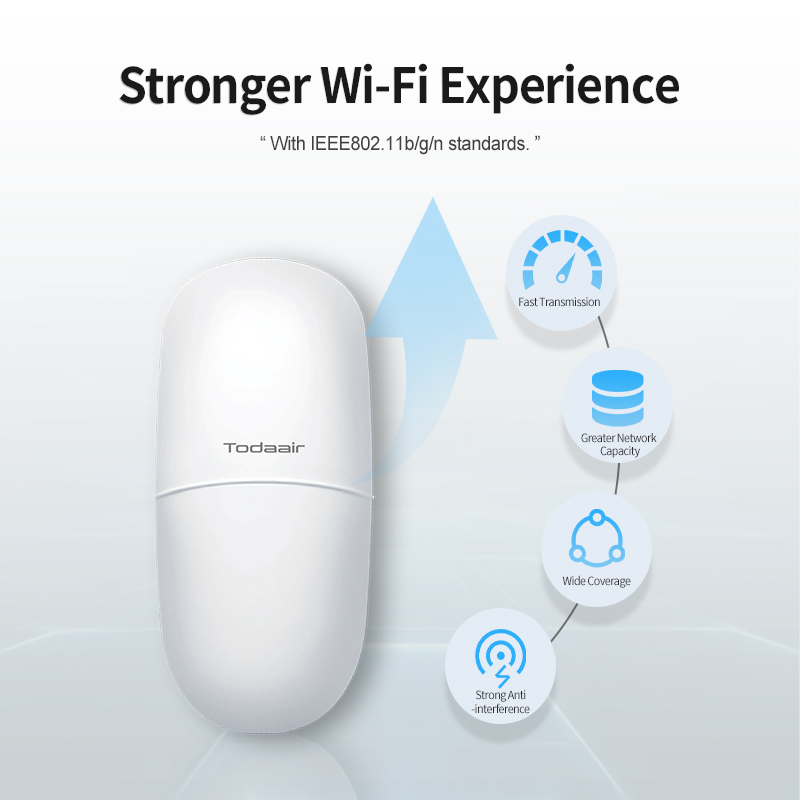
l The device complies with IEEE 802.11b/g/n standards, delivering enhanced transmission performance, including higher speeds, wider bandwidth, lower latency, and extended coverage.
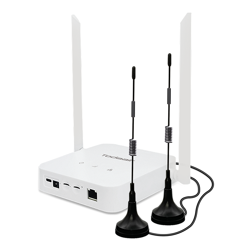
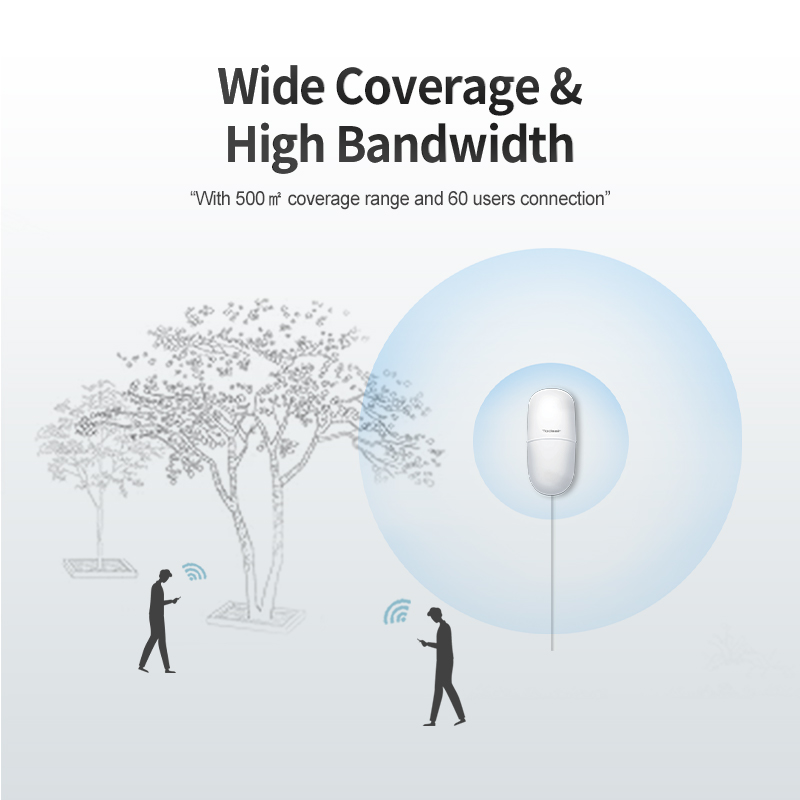
l The device features 27dBm transmission power with four built-in high-gain omnidirectional antennas, ensuring stable coverage of up to 500m². It supports high-density connectivity for up to 60 concurrent wireless terminals while maintaining optimal signal quality.
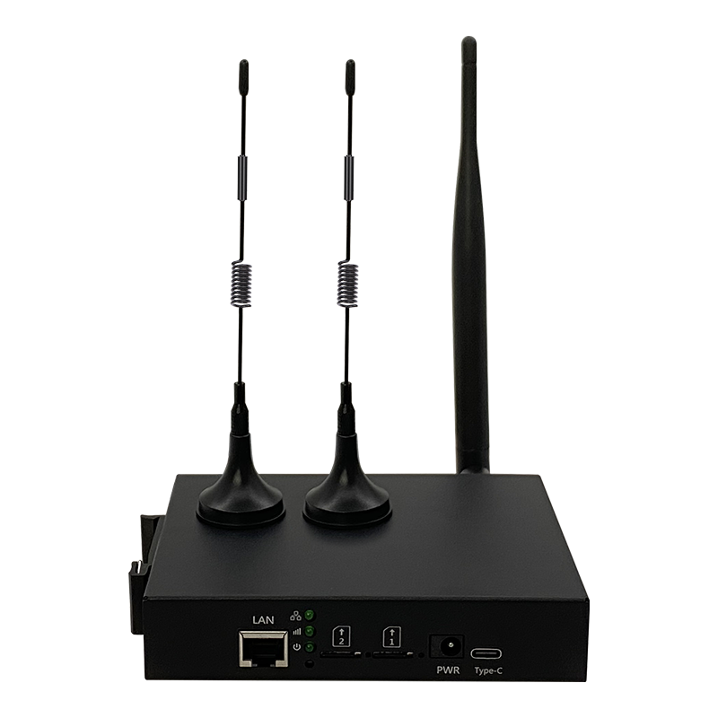
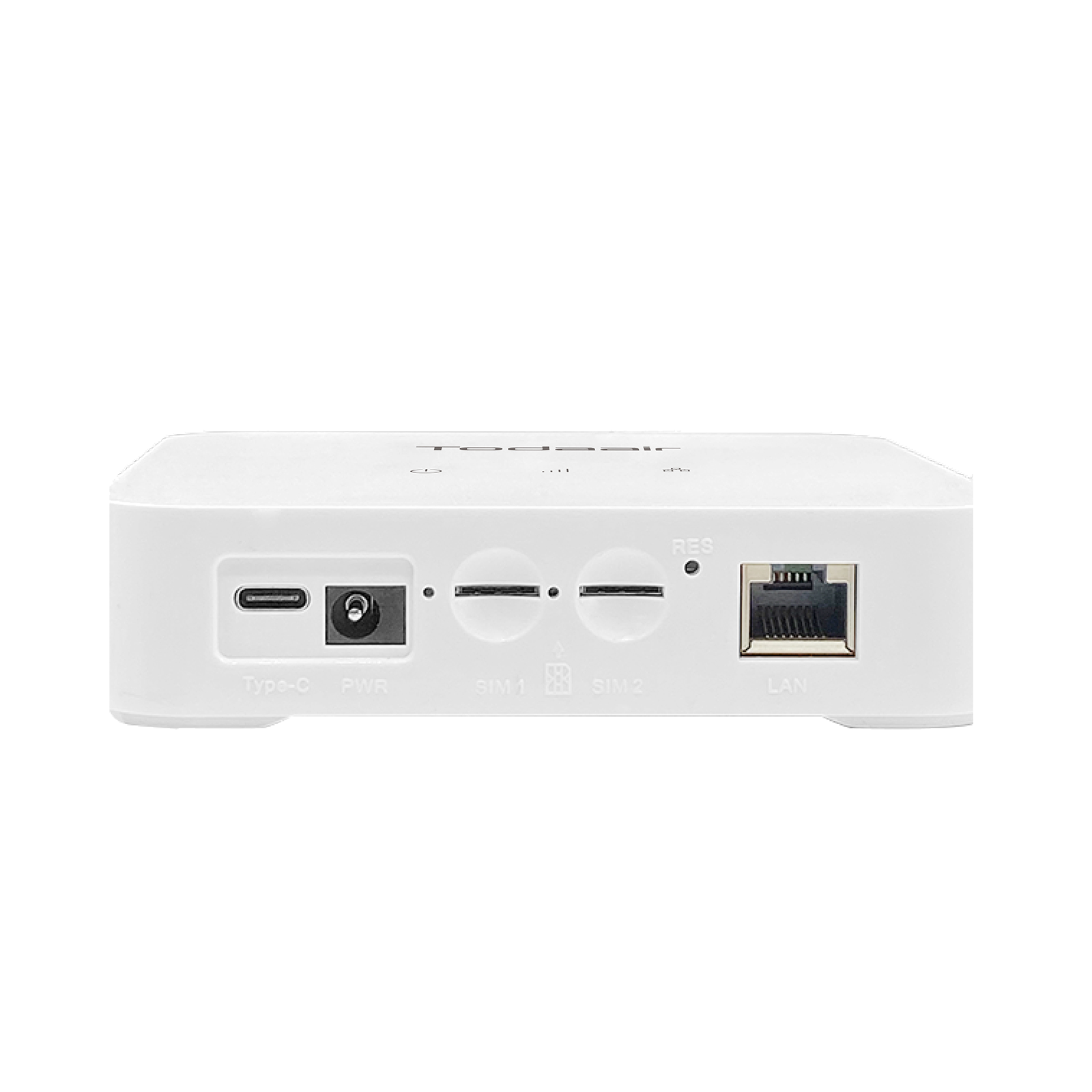
l The device integrates a Nano-SIM card slot supporting 3G/4G multi-mode operation. Its dual-SIM (single standby) design enables flexible network deployment, while cable-free, plug-and-play cellular connectivity ensures instant operation.
l The device operates in the 2.4GHz frequency band, featuring advanced anti-interference technology, enhanced signal penetration, and high-throughput transmission, and achieves maximum data rates of up to 300Mbps.
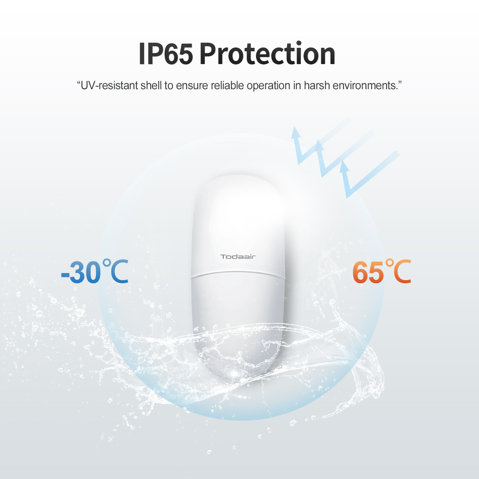
l Features UV-resistant housing with IP65 ingress protection and an operating temperature range of -30°C to 50°C (-22°F to 122°F). The optimized thermal management system ensures stable performance under extreme outdoor conditions.
l The device is equipped with 2* 10/100Mbps Ethernet ports for wired connections and supports power input via PoE 24V power supplies. It offers flexible deployment options suitable for diverse installation scenarios.
| Pole-Mount | |
 |
 |
|
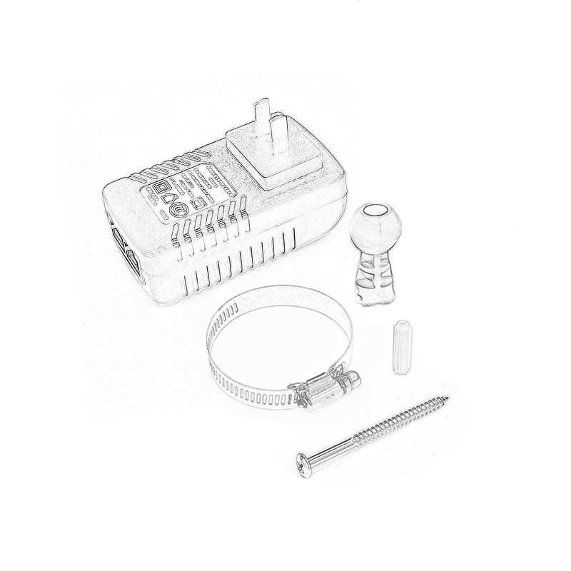
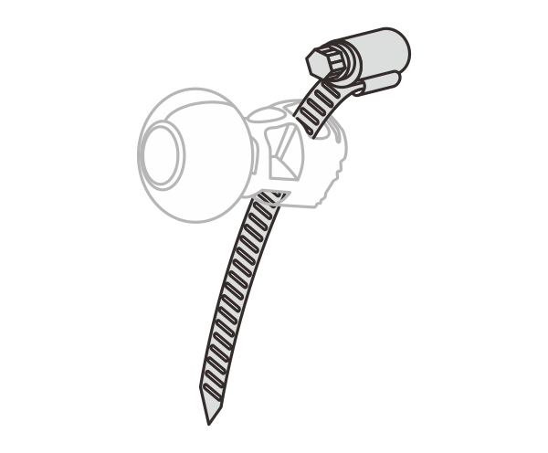
1 Route the strap through the lower slot of the universal joint bracket, then secure it by bucking. |
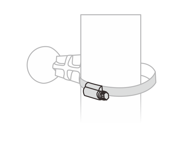
2 Wrap the strap around the pole, then use a screwdriver to tighten the mounting screw. |
 |
 |
|
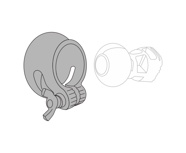
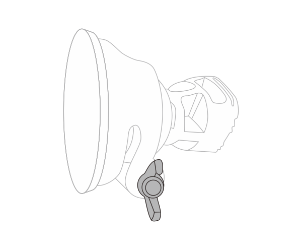
3 Align the device’s mounting interface with the universal joint bracket. Insert the bracket assembly into the lock ring, ensuring the device back contacts the ring surface. |
4 Securely tighten the fixing screw, while maintaining 0.5-1mm axial play in the lock ring for pivot adjustment. |
| Wall-Mount | |
 |
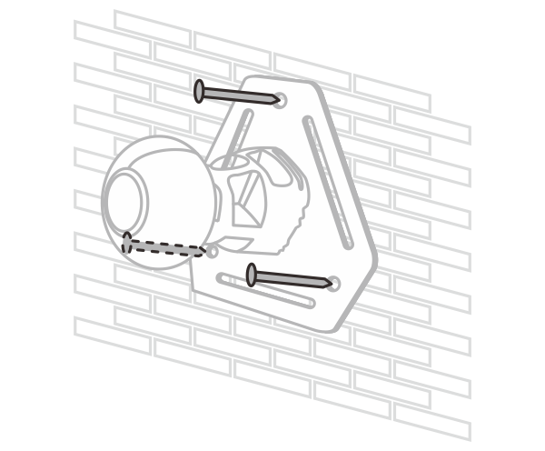 |
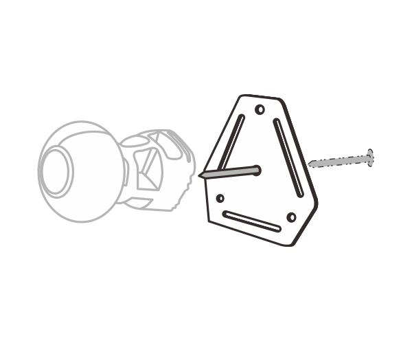
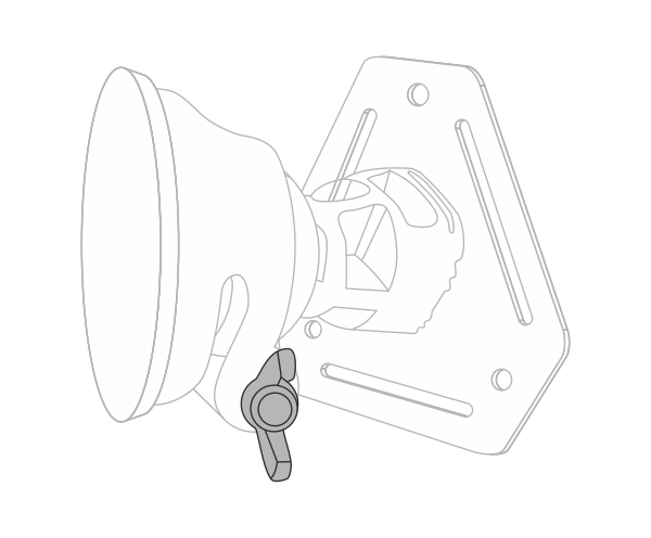
| 1 Secure the wall mount plate using the anchor bolts. Attach the universal joint bracket to the plate with the screws. |
2 Securely fasten the wall mount plate to a load-bearing wall using appropriate anchors. |
 |
 |
|
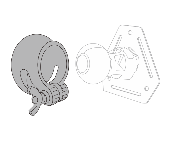
3 Attach the device to the universal joint bracket. Inset the bracket into the lock ring with the device’s back surface facing outward. |
4 Securely fasten the positioning screw while maintaining 0.5-1mm axial clearance on the lock ring to enable device pivoting.
|